Cessna 172 Simulator

Tuesday, January 12, 2010

This is the blog of my old simulator. I recently I started a new project. The blog for this can be found here:

http://www.cessnaglasscockpit.blogspot.com/

Thanks

Rhydian

Saturday, January 19, 2008


I got a new camera for Christmas so here are some more high quality pictures to look at.


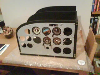
This is what my simulator currently looks like (19/01/08). I am very pleased with the outcome so far. It has been placed on a modified overhead projector table. The steel tubes that usually hold the projector were cut off with an angle grinder,the whole table was then stripped down, painted with matt black and put back together again. As you can see, the table has wheels so it's easy to move around. It really benefits from having them because the sim has gotten very heavy. There are some changes to be made with the case design which haven't been finished. I need to cut the case down to be the same size as the table. As you can see from the picture it is hanging over the table at the moment. If I leave it like this it will not fit into the study. This is how tight I am for space in my new house. There are still things missing, such as the avionics (which will go on the right side, I intend to buy the GoFlight Rack but i'm not sure whether to make my own panels and electronics or buy their modules) some instruments, such as engine, navigation and clock have to be placed. The throttle and mixture controls need to be designed and coinstructed and so does the yoke! (Unfortunately I can't use Simkit's version, it's too expensive and far too big to fit in the case. So I'm going for a custom design. Yikes! The screens need to mounted on LCD mounts as well. So, there is an awful long way to go. However, I anticipate, that the sim will be actually UP and RUNNING for the first time next week! I'll post some more pictures soon.

Saturday, September 29, 2007


After 3 years I have finally ordered the CCU2 from Simkits (The circuit board that controls the instruments). It took me long enough. I think at one point I just said to myself "Ahhh...bugger it..where's my credit card"!!! So I am now sitting patiently waiting for it to be delivered. Here is a small (mobile phone) rather bad quality photo of my current setup. The photograph really doesn't do it justice. I have just found a projector table for the whole sim to bolt onto, so there is an awful lot of work to do. It just about fits into my new house...I think. I'm hiring a rather nifty camera (D70) from the photography department at the university to take some higher quality photos to share with anyone who is interested.

R

Friday, April 13, 2007


Myself and Sam today completed the inner casing out of MDF. How we got this done today, I do not know. After belting the crap out of each other with some plastic pipe (I'm in my late twenties for crying out loud!) I was amazed at how we completed it on time. I'm very pleased at how its turned out. I have added some toggle switches that i bought from Maplin (1 toggle switch = £2.26...that doesn't seem very cheap to me), and I think this has really brought the panel to life. I had a slight panic attack last night because I thought I had bought the wrong circuit board. For some reason I had it in my head that a "Digital-32 input controller" could not take a toggle switch. Uhhh. .. After a sleepless night worrying about it...seriously, I'm sure there is plenty more things to worry about, a quick email from Peter at Simkits put my mind at rest. So basically I need some more switches, some PCB holders to put the controller in place and then some wiring and firing to light this baby up. Yeehah.

Labels:

Thursday, April 12, 2007


Some progress has been made building the case for the panel. With the help of my mate Sam, a very talented theatre technician, great fella, even better to have around when your drunk and can't find your own house, this is the second attempt at using MDF for the casing. Sam practically built this for me and it's great to have someone with more experience in carpentry working with me on this project. Our first attempt had slight design flaw and it may have worked if we hadn't cut the wood so thin. It unfortunately split apart and I had to go back to the drawing board. But this was the result and I think it works quite well and it's very sturdy. Three more pieces which we are cutting tomorrow and the circuit board can be put in place ready for everything to be wired up. This project is moving at quite a quick pace now and I can't wait to start using it.

Labels:

Saturday, April 07, 2007


I have finally managed to paint and engrave my panel and I am very happy with the result. The engraving shop said that they were not entirely sure that vinyl lettering would be suitable for the type of pain on the panel. They were worried that when peeling away the surplus vinyl the paint could come away from the panel. It was actually flaking away in my hands at one point. The paintshop had sprayed the aluminium the wrong colour. It was in very light grey. So it had to be repainted black and they ended up doing a quick job. Subsuquently it wasnt baked in an oven but it still looks very good. It was decided that laser engraving was a better option but the shop was not sure how deep it would cut. But to my surprise the engraving took away the first layer of paint leaving the previous grey underneath and it really looks superb.

I have bought some MDF to make the case for this panel to be attached to which I will start on Monday. But it is really starting to shape up.

Labels:

Sunday, October 29, 2006

Current Projects.

NMK SE

All the panel's round holes have been filed down to take a standard toggle switch. The rectangular holes have been filed down to take dual rocker switch units that I bought from RS (Radio Spares). They fit really well (they aren't pushed in properly in the photo) it all feels really solid. A few things are left do:

1. Paint the panel.
2. Stencil it - from a specialist firm that specialises in vinyl lettering.
3. Design and make the housing for the unit, out of wood or metal, I'm not sure yet.
4. Fit and wire up the circuit board with all the switches.
5. Finally, test it to make sure it works correctly in FSX.

CESSNA SIMULATOR - 'PRIMARY 6' PROJECT

Due to certain circumstances like getting married and buying a house (Damn it...I have to do grown up things now!!!), I am continuing with what I have built so far. So, this means that my primary 6 project will now be in full swing and be completed by Christmas (because I am getting the CCU board as a Christmas present). An enclosure will be made to contain the panel, the CCU to operate the instruments and a standard PSU to power everything. The turn co-ordinator and warning panel will also be fitted so that the 'primary 6' will be a fully working unit that I can use with FSX. The other great thing is that it will be very portable.

Now all I have to do is finish these projects off before I start getting ideas for anymore!